
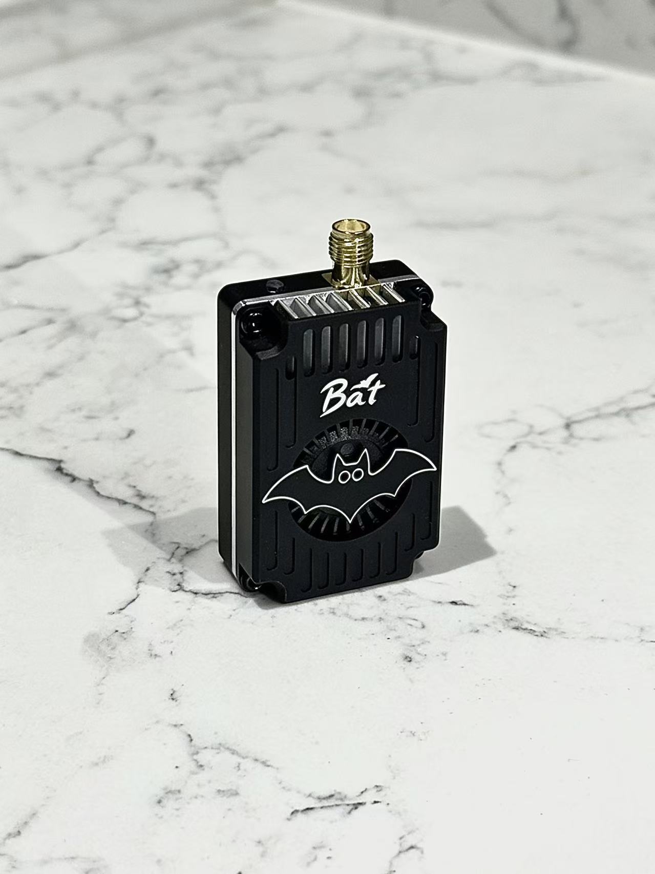
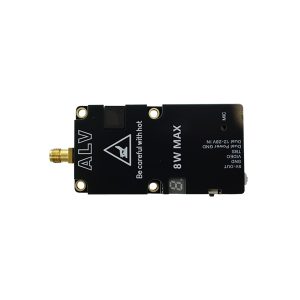
4.3GHz 5W Video Transmitter
-Designed for long-range flights, up to 5W transmitting power, and provide multi-level adjustment.
-Efficient PA and power calibration to ensure power consistency across all channels.
-Customized digital PLL circuit, chip level integration, no frequency drift.
-Aluminum alloy three-layer shell structure and large centrifugal fan provide sufficient heat dissipation to ensure stable output of transmitting power.
4.3GHz 5W Video Transmitter
Features
-Designed for long-range flights, up to 5W transmitting power, and provide multi-level adjustment.
-Efficient PA and power calibration to ensure power consistency across all channels.
-Customized digital PLL circuit, chip level integration, no frequency drift.
-Aluminum alloy three-layer shell structure and large centrifugal fan provide sufficient heat dissipation to ensure stable output of transmitting power.
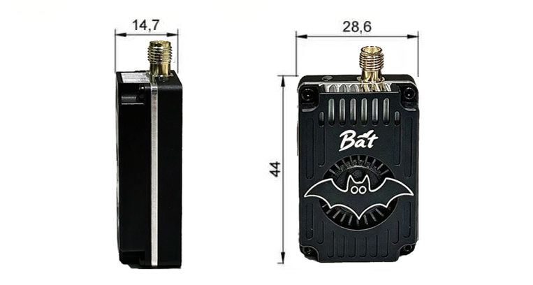
Diagrams
General Characteristics
| Frequency band | 3700-4320MHz | Frequency precision | ±200KHz (Typ.) |
|---|---|---|---|
| Channel customer | 32 | S/N(For ±3MHz) | >55dBc |
| Modulation type | FM | Antenna Port | SMA 50 Ohms |
| Frequency control | PLL | Video input level | 1V±0.2Vp-p (typ.) |
| Frequency stability | ±100KHz (Typ.) | Operating Temperature | -10℃~+70℃ |
| Power Supply | DC 7-30V | Control Protocol | IRC Tramp |
RF output
| CH1 | CH2 | CH3 | CH4 | CH5 | CH6 | CH7 | CH8 | |
|---|---|---|---|---|---|---|---|---|
| BAND A | 3700 | 3720 | 3740 | 3760 | 3780 | 3800 | 3820 | 3840 |
| BAND B | 3860 | 3880 | 3900 | 3920 | 3940 | 3960 | 3980 | 4000 |
| BAND C | 4020 | 4040 | 4060 | 4080 | 4100 | 4120 | 4140 | 4160 |
| BAND D | 4180 | 4200 | 4220 | 4240 | 4260 | 4280 | 4300 | 4320 |
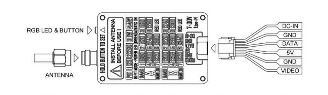
Wiring
-
Antenna must be connected before use! Otherwise there is a risk of damage to the product.
-
The product needs to be mounted reliably, avoiding vibration and high temperatures.
-
The product has a built-in power filter, but still need to avoid excessive power supply interference.
Settings
-
Controlled using a single button, the button integrates RGB lighting, blue for band, red for channel, and green for power level.
-
When there is no operation, the RGB LED blinks cyclically, the number of times the RGB blinks represents the current VTX status (when the green LED is always on, the VTX enters PTTMODE).
-
Long press the button to enter VTX setting, at this time the RGB lights are lit alternately, release the button under the corresponding color light to enter the corresponding function setting. At this time, short press the button to adjust the value.
-
For setup via the flight controller, connect the DATA pin and use the IRC Tramp protocol.

Reviews
There are no reviews yet.