
1500VDC Solar Surge Protector | 40kA Type 1+2 DC SPD for PV Systems
CYD1-GD-PV series surge protector, protect against lightning surge voltages in solar system.They must be installed in parallel on the DC networks to be protected and provide protection.
https://www.ppspd.com/1500VDC-Solar-Surge-Protector-40kA-Type-1-2-DC-SPD-for-PV-Systems.html
CYD1-GD-PV s series surge protector, protect against lightning surge voltages insolar system (photovoltaic power supply system).These units must be installed in parallel on the DC networks to be protectedand provide common and different modes protection. lls inslalled location arerecommended at both ends of the DC power supply line (solar panel side andinverter/converler side), ely if the line routing is external and long.High energy MOVs equipped with specific thermal disconnectors and relatedfailure indicators
Technical data
|
Model |
CYD1-GD-PV |
||||
|
SPD according to EN 61643-31 / IEC 61643-31 |
type 2 / class II |
||||
|
UCPV( DC) |
500V |
800V |
1000V |
1200V |
1500V |
|
Nominal discharge current (8/20 μs) In |
20 kA |
||||
|
Maximum discharge current (8/20 μs) Imax |
40 kA |
||||
|
Voltage protection level Up |
2.5kV |
3.2kV |
4.0kV |
4.0kV |
4.5kV |
|
Response time tA |
25 ns (L-N) |
||||
|
Residual current a.c. and d.c. IPE |
0.3 mA(DC), 0.3 mA(AC), |
||||
|
Humidity range |
5% … 95% |
||||
|
Range of operating temperatures TU |
-40°C … +70°C |
||||
|
Atmospheric pressure and altitude |
80k Pa … 106k Pa, -500 m … 2000 m |
||||
|
Operating state / fault indication |
Green ok / Red defect |
||||
|
Number of ports |
One port |
||||
|
Cross-sectional area (max.) |
2 AWG (Solid, Stranded) / 4 AWG (Flexible) 35 mm2 (Solid, Stranded) / 25 mm2 (Flexible) |
||||
|
For mounting on |
35 mm DIN rail acc. to EN 60715 |
||||
|
Enclosure material |
V0 fireproof material |
||||
|
Place of installation |
indoor installation |
||||
|
Degree of protection |
IP 20 |
||||
|
Poles |
1P、 2P、 3P |
||||
Remote Contact Signaling
|
Type of remote signalling contact |
C+NC: Normally closed C+NO: Normally open C: Common contact |
| a.c. switching capacity |
250V / 0.5 A |
|
d.c. switching capacity |
250V / 0.1 A; 125 V / 0.2 A; 75 V / 0.5 A |
|
Cross-sectional area for remote signalling terminals |
max. 1.5 mm2 solid / flexible |
|
Remote signalling alarming mode |
Normal: closed; failure: open-circuit |
|
Acessibility |
Inaccessible |
|
Protection fuction |
Overcurrent |
|
PV earthing system |
Earthed and Unearthed (both) |
|
SPD failure mode (OCFM/SCFM) |
OCFM |
Circuit diagram
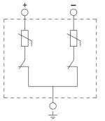
2P
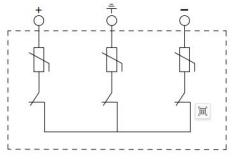
3P
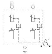
2P+R
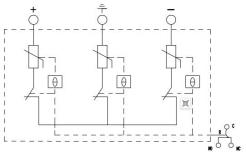
3P+R
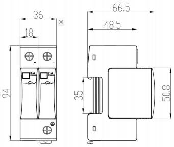
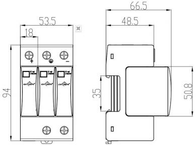
Drawings
2P
3P
Installation, Usage and Maintenance
This product can only be installed and maintained by qualified professionals. The installation position cannot be touched by hands. Ensure that it is unpowered and check whether the SPD is all right before installation. If there’s damage or the display window is red, the SPD cannot be used any more; if the window is green, the SPD is normal.
The installation of SPD should be based on Fig. 3 IEC 60364-5-53. The cross-sectional area of ground wire should not be less than 4 mm2, and the length of total lead not more than 0.5m.
The minimum distance from any earthed conductive surface at which the SPD can be installed is 8mm.
Connection of remote signalling alarm: the SPD is provided with remote signalling interfaces (NC, COM and NO, normally closed), applicable for remote centralized monitoring or alarm.
After the connection, check if the module is fitted in. If so, NC and COM are closed; if not, repress the module.
Installation Diagram
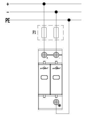
2p
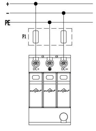
3p

Reviews
There are no reviews yet.