
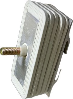
Description
In modern power distribution systems, busway systems provide an efficient way to transmit and distribute electrical power across industrial facilities, commercial buildings, and large infrastructure projects. However, the reliability of a busway system depends not only on the busbar conductors themselves but also on the quality of the connections between individual sections.
A busbar connector is a critical component that joins two busway sections or connects a busway system to compatible electrical equipment. It creates a continuous electrical path while maintaining mechanical stability, insulation separation, and grounding continuity.
For electrical equipment manufacturers, contractors, and power distribution system integrators, understanding the structure and performance of a busbar connector is essential for selecting suitable components and ensuring reliable system operation.
1. What Is a Busbar Connector?
A busbar connector is an electrical connection assembly used to join the conductive components of two busway sections. It is designed to provide a secure electrical connection while maintaining the required insulation distances and mechanical strength.
A typical connector assembly consists of conductive copper plates, grounding connection plates, insulation partitions, fastening components, and a protective cover.
These components perform different functions but work together as an integrated connection system. The conductive plates establish electrical continuity, the insulation components separate different electrical phases, and the fastening system maintains appropriate contact pressure.
A precision cast-aluminum structure provides mechanical support and helps protect the connection assembly. Depending on the design, the connector may also incorporate thermal compensation components to maintain stable clamping pressure during temperature changes.
2. Main Components of a Busbar Connector
The performance of a busbar joint depends on the quality and coordination of its individual components. Each part contributes to electrical conductivity, insulation safety, mechanical stability, or environmental protection.
Conductive Connection Plates
The conductive connection plates are among the most important components of a busbar connector.
Typically manufactured from T2 copper, these plates feature tin-plated or silver-plated surfaces. They clamp the conductor ends of two busway sections, increasing the effective contact area between the conductors.
A larger and properly maintained contact area helps reduce contact resistance and improve electrical conductivity. This is particularly important because excessive resistance at a connection point can result in localized heating during operation.
The surface plating also helps maintain reliable electrical contact and provides additional protection against surface oxidation under suitable operating conditions.
Grounding Connection Plate
The grounding connection plate connects the busway housings or protective earth conductors, maintaining grounding continuity throughout the distribution system.
A reliable grounding connection is essential for electrical safety. It provides a conductive path for fault current and supports the proper operation of protective devices when an electrical fault occurs.
Insulation Partitions
Insulation partitions separate the A, B, C, N, and PE conductive components within the connector assembly.
Common materials include heat-resistant epoxy board, SMC, and DMC. These materials provide electrical insulation and mechanical support while maintaining the required phase spacing.
Proper insulation separation helps prevent phase-to-phase and phase-to-ground short circuits, supporting the safe operation of the busway system.
Bolt Insulation Sleeve and Insulating Washer
The bolt insulation sleeve isolates the metal fastening bolt from energized conductive components, helping prevent unintended electrical bridging between different phases.
The insulating washer positions the conductors and limits unwanted movement during assembly. It also helps distribute mechanical pressure and protects the insulation partitions from cracking or other damage caused by excessive compression.
Torque-Locking Bolt and Nut
The torque-locking bolt is designed to provide consistent clamping pressure during installation.
Its break-off torque structure gives installers a clear indication when the specified tightening torque has been reached. This helps reduce the risk of insufficient tightening or excessive compression.
Maintaining appropriate clamping force is important because loose connections can increase contact resistance, while excessive tightening may damage insulation or other mechanical components.
Flat Washers, Spring Washers, and Disc Springs
Temperature changes can cause conductive components and surrounding materials to expand or contract. Over time, these dimensional changes may affect the pressure maintained at the connection point.
Flat washers, spring washers, and disc springs help compensate for these changes by maintaining more consistent mechanical pressure.
This arrangement helps reduce the risk of joint loosening and abnormal temperature rise during long-term operation.
Connector Protective Cover
The protective cover encloses the connector assembly and is generally manufactured from aluminum alloy or galvanized steel.
It helps prevent dust, foreign objects, and accidental contact with energized components. The specified joint protection level is IP54, providing protection against dust ingress to a level that does not interfere with satisfactory operation and protection against water splashing from any direction.
The actual protection performance depends on correct assembly, sealing, and installation conditions.
3. How Does a Busbar Connector Improve Power Distribution Reliability?
A reliable busbar connection requires more than simply joining two copper conductors. It must maintain electrical contact, mechanical stability, and insulation performance under normal operating conditions.
Several design features contribute to this objective.
Low Contact Resistance
The T2 copper conductive plates provide a large contact area between connected busway conductors. With suitable surface treatment and correct installation, the connector can achieve a contact resistance of no more than 50 μΩ according to the supplied technical reference.
Lower contact resistance helps control heat generation at the joint.
Stable Mechanical Clamping
The torque-locking bolt and spring components help maintain the required clamping force. This reduces the likelihood of connection loosening caused by vibration or temperature fluctuations.
Reliable Electrical Insulation
Heat-resistant insulation partitions and bolt insulation sleeves maintain separation between different conductive phases. This helps reduce the possibility of electrical faults within the connector assembly.
Continuous Grounding Protection
The grounding connection plate maintains the electrical connection between busway housings or PE conductors, supporting grounding continuity throughout the system.
External Protection
The protective cover provides an additional barrier against dust, foreign objects, and accidental contact, helping protect the connection area in industrial and commercial environments.
4. Busbar Connector Assembly and Installation Process
Correct assembly is essential for achieving the intended electrical and mechanical performance. The connector should be installed according to the manufacturer's technical documentation and the applicable electrical safety requirements.
The general assembly process includes three main stages.
Step 1: Bond the Conductive and Insulating Components
First, the insulation partitions, conductive connection plates, and grounding connection plate are bonded together using resin adhesive.
The bonded assembly must remain stationary until the adhesive has fully cured. This helps maintain the intended component positioning and structural integrity.
Step 2: Assemble the Protective and Fastening Components
Next, install the processed connector protective plate together with the torque-locking bolt, spring washer, and bolt insulation sleeve.
Each component should be positioned correctly to ensure proper insulation separation and mechanical assembly.
Step 3: Complete Connector Assembly and Installation
Insert the bonded insulation and conductive assemblies onto the bolt in the specified sequence. Install the protective plate and pre-tighten the connector.
During final installation, connect the assembly securely to both busway ends using the appropriate installation tools and procedures.
Before energizing the system, qualified personnel should verify the connection, grounding continuity, insulation condition, and tightening requirements in accordance with the manufacturer's instructions and relevant electrical standards.
5. Important Factors When Selecting a Busbar Connector
Choosing a suitable busbar connector requires attention to the electrical specifications and mechanical design of the complete busway system.
The following factors should be considered:
-
Electrical compatibility: Confirm that the connector matches the busway system's rated voltage, current, conductor arrangement, and phase configuration.
-
Conductive material: Check the copper grade and surface treatment of the conductive plates.
-
Insulation performance: Evaluate the insulation materials and phase separation design.
-
Contact resistance: Review the specified contact resistance and applicable testing requirements.
-
Mechanical fastening: Confirm the torque-locking mechanism and installation procedure.
-
Environmental protection: Check the protective cover design and required IP protection level.
-
System compatibility: Ensure the connector dimensions and structure match the specific busway model.
Selecting a connector based only on its external dimensions or appearance may lead to installation problems. Compatibility with the complete busway system should always be confirmed before procurement.
6. Technical Specifications at a Glance
The following table summarizes the main technical reference information for this busbar connector.
| Parameter | Technical Specification |
|---|---|
| Conductive Plate Material | T2 copper |
| Conductive Surface | Tin-plated or silver-plated |
| Insulation Materials | Epoxy board, SMC, or DMC |
| Protective Cover Material | Aluminum alloy or galvanized steel |
| Contact Resistance | ≤ 50 μΩ |
| Reference Standard | GB 7251.2 |
| Joint Protection Level | IP54 |
These specifications provide a starting point for technical evaluation. Buyers should also confirm rated current, rated voltage, temperature-rise limits, dimensions, and compatibility with the intended busway system.
Conclusion
A busbar connector plays an important role in maintaining electrical continuity and mechanical stability throughout a busway power distribution system. Its performance depends on the combined functions of conductive copper plates, grounding components, insulation partitions, torque-locking fasteners, thermal compensation elements, and protective covers.
By controlling contact resistance, maintaining stable clamping pressure, ensuring insulation separation, and protecting the connection area, a properly designed connector helps support reliable long-term power distribution.
For electrical contractors, system integrators, and equipment manufacturers, selecting the correct busbar connector and following the specified installation procedures are essential steps toward building a safe and dependable busway system.
Reviews
There are no reviews yet.